

Conductor stranding refers to stranding several single wires with the same or different diameters together in a certain direction and according to certain rules to form an overall stranded wire core. Large cross-section solid conductors cannot be laid, formed and connected smoothly because they are not easy to bend. Stranded conductors solve this problem. The stranding methods depends on the metal and its properties.
Concentric Stranding
This is the typical way that power cable conductors are twisted. Consists of a center line or a core surrounded by one or more layers of spirals. Each following layer add six more wire cores than the previous layer. Except for conductors that are stranded in one direction, each layer is laid in the opposite direction to the layer below. For the conductors of power cables, the core is a single wire, and the twisted wires are all of the same diameter. As shown in the figure, the first layer outside the wire core is 6 wires; the second layer is 12 wires; the third layer is 18 wires; and so on. The distance that a single wire of a conductor completes a complete spiral within a layer is called the pitch. The pitch requirements are specified in Part 4 of the ASTM standard. The pitch should be between 8 and 16 times the outer diameter of the corresponding lay layer.
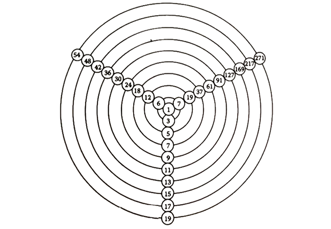
In power cables, the stranding standard is Class B. The standard requires that the outermost twisting direction should be left. This means that when viewed along the axis of the cable conductor, the outermost strands are twisted to the left as they leave the observer. Better flexibility is obtained by increasing the number of single wires in the conductor. Class C has one more single wire layer than Class B, and Class D has one more single wire layer than Class C. Level settings all the way up to level M (commonly used for welding cables etc.). Class C and Class D conductors are similar in weight to Class B conductors and have outer diameters within 3 mils greater than Class B conductors. n=1+3N (N+1) can be used to calculate the number of single wires of concentrically stranded conductors. In the formula, n is the total number of single wires in the stranded conductor; N is the number of layers outside the central single wire.
Compact Stranding
This concept describes the tight integration of the stranded layers through slight deformation. The conductor area is not reduced. The diameter of the final compacted conductor can be reduced by no more than 3% compared to the equivalent diameter of ordinary concentrically stranded core conductors. The common reduction is 2.5%.
Reducing the conductor outer pitch can solve this problem, but results in high impedance and requires the consumption of more conductor material.
Compact stranding is the more common stranding method because the pitch set in concentric stranding creates tiny gaps between the layers of conductors. The low-viscosity material "falls" into these gaps after extrusion. This results in surface irregularities, increases the voltage to be withstood, and makes the layer more difficult to peel off.
Profile Line Stranding
This method is similar to compaction stranding, except that the additional forming process allows the conductor diameter to be reduced by 9% compared with the diameter of ordinary concentrically stranded conductors. Resulting in a conductor diameter that is approximately that of a solid conductor. However, the air gap still exists as a migration channel for moisture. The main advantage of profiled stranded conductors is the reduced conductor diameter.
Bunch Stranding
This concept is used to describe the centralized twisting of single wires in a uniform direction without considering the geometric arrangement.
This structure is used for cables with small American wire gauge conductors that require extremely high flexibility, such as portable cables used in vacuum cleaners, lawn mowers, etc.
In Class K and Class M conductors, the single wire diameter is constant. The required conductor cross-sectional area is met by increasing the number of single wires.
Multi stranding
This concept is used for concentric stranded conductors where each single wire is also stranded. That is, a collection of concentric conductors and bundled conductors. The final conductor is constructed from a concentric assembly of bundled or coaxially stranded conductors. Each group is made up of a certain number of single wires, rather than a single wire. The description of a multi-stranded conductor shall give the number of groups of strands and the number of single wires in each group.
Class G and Class H cables are commonly used for mining portable cables. Class I, Class L, and Class M cables use twisted cables to form concentric cables with the same single wire size. The required cross-sectional area size can be achieved by increasing the number of wires. Class I cables use #24AWG (0.020in) single wire, Class L cables use #30AWG (0.010in) single wires, and Class M cables use #34AWG (0.0063in) single wires. Class I cables are typically used on railways, while Class L and Class M cables are used in more portable applications such as welding cables and mobile power cords.
Fan Shaped Conductor
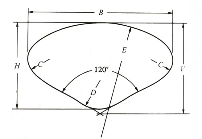
A conductor whose cross-section is approximately fan-shaped is called a fan-shaped conductor. A typical three-conductor cable has three 120° sectors, which form the basic shape of a circular cable. Such cables have a smaller outer diameter than corresponding concentric conductor cables and can exhibit lower AC impedance due to reduced proximity effects.
For paper-insulated cables, the sector conductors are mostly twisted and compacted to obtain the highest possible ratio of conductor cross-sectional area to cable cross-sectional area. The exact shape and dimensions of each manufacturer's products vary slightly.
Picture shown a typical compressed fan-shaped conductor ratings.
To a certain extent, solid rather than stranded sector conductors have been used in low-voltage cables, and there have been attempts to use such conductors in medium-voltage cables, but this has not yet been achieved due to economic considerations at the time.
Milliken Conductor
Milliken conductors are circular and consist of three or more strands twisted together and separated by a thin insulation layer. Each block carries a smaller current than the entire conductor, and the current is transmitted through the inner and outer locations of the entire conductor. The advantage of this structure is that the skin effect is lower, and the smaller skin effect makes the AC impedance lower than the traditional twisting method.
This form of conductor should be considered for use in cables such as 1000kcmil (corresponding to metric 507mm²) and larger cross-sectional areas that carry large currents. The diameter of a quarter conductor is approximately equal to the diameter of a Class B concentrically stranded conductor.
Annular Conductor
Annular conductors are circular stranded conductors in which individual wires are stranded around a central fiber rope, threaded metal pipe, or I-shaped beam. The advantage of this type conductor is that for a conductor with a certain cross-sectional area, the influence of the skin effect at the center can be eliminated, making the overall AC impedance smaller. Subject to space permitting, ring conductors are more economical for cables with a cross-sectional area of 60Hz, 1000kcmil and above, and for cable conductors with a cross-sectional area of 1500kcmil (corresponding to 760mm² in the metric system) and above under low-frequency conditions (such as 25Hz).