

Abstract: Selecting reasonable cable structures and cabling process parameters can help improve cable performance and reduce production costs. This article mainly describes common problems and solutions in the cabling process of high-voltage cable milliken conductors and medium-voltage cable.
1.Twisting direction of cabling
The twisting direction of the cabling can be divided into S and Z directions. The method of differentiation is the same as that of stranded wire cores. After the insulated wire core is cabled, place it horizontally and look forward. If it is twisted left, it is S, and if it is twisted right, it is Z, the cabling of outermost layer of the cable should be Z. During the production process, facing the front end of the stranding machine or cabling machine, the stranding cage rotates clockwise, and the direction of twisted wire core is Z, and the reverse direction is S. To determine the twisting direction of the twisted wire core, you can use your hands to compare. The thumb should be along the axis of the cable core, and the other four fingers should be in the same direction as the twisted wire. If it is the same as the left hand, it is S, and if it is the same as the right hand, it is Z. As shown in Figure (1).
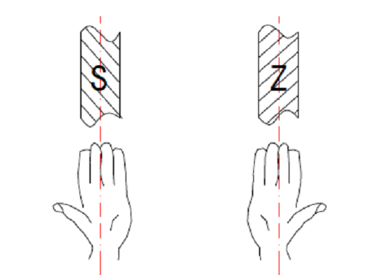
Figure (1) Determination of twisting direction
2.Cabling pitch and pitch factor
During the cabling process, each insulated wire core of the cable has both linear and rotational motions. When the insulated wire core rotates once, the distance that the insulated wire core advances along the axial direction is called the cable pitch. In production practice, the cable pitch is generally expressed in terms of pitch multiples. The so-called pitch multiple is the ratio of the pitch length to the diameter of the cable. Expressed as:
m=L/D
In the formula, m——cable pitch factor; L——cable pitch; D——cable diameter.
The pitch factors are different for different products. Cables that generally require higher flexibility require smaller pitch factors. For example, for electric drill cables in mining cables, the UZ standard stipulates that it should not be greater than 5 times, the UC standard and UCP standard stipulate that it should not be greater than 10 times, and the U and UP standards stipulate that it should not be greater than 12 to 14 times, so that these cables have better bending properties.
The selection of cable pitch length is different for different cable insulated cores. The size of the cable pitch directly affects the deformation of the insulated core and the flexibility of the cable. The larger the cable pitch, the greater the deformation of the cable insulation core when bending, and the worse the cable flexibility.
Usually the cabling pitch of the insulated wire core is selected based on factors such as the cable usage conditions, the softness of the wire core, and the stability of the cable after cabling. Select the appropriate cable pitch to ensure that the cable has good structural stability and bendability, reduces deformation and wrinkles, and has greater productivity. For circular insulated wire cores, floating cables are used and smaller pitches are used. Generally, the pitch ratio is 25 to 40, while fan-shaped insulated wire cores are fixed and cabled. In order to reduce deformation and strip displacement, larger pitch ratios are used. The pitch ratio is generally between 40 and 80. Commonly used pitches are shown in Table (1).
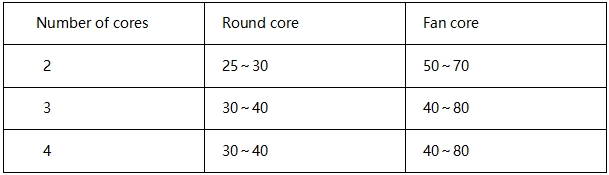
Table (1) Cable pitch ratio of paper insulated wire cores
In the specific selection, generally the larger the cross-section of the stranded core, the smaller the cable pitch ratio. Cables with smaller cross-sections usually have a pitch ratio of 70 to 80, while cables with larger cross-sections usually have a pitch ratio of 60 to 70. Because when a large cross-section cable is formed into a cable, if the pitch is too large, the flexibility will become poor and unstable. When the extruded insulated wire core is formed into a cable, the insulated wire core is relatively rigid and generates large internal stress. In order to ensure its structural stability and prevent serpentine formation after the cable is formed, a smaller pitch should be selected, as shown in the Table ( 2) as shown.
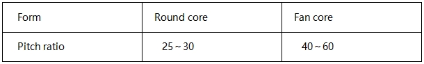
Table (2) Cable pitch ratio of extruded insulated wire cores
The cable pitch of the control cable is small, and the cable pitch factor is generally 18 to 20 for the outer layer and slightly larger for the inner layer.
3. Twisting pitch and rate
Since the insulated wire core moves in a straight line and twists during the cable cabling process, the length of the cable is not equal to the actual length of the insulated wire core. Within a pitch of the cable, the ratio of the actual length l of the insulated core to the pitch length L is called the twisting coefficient K, that is, K=l/L.
In actual use, there is also the concept of twisting rate, that is, the ratio of the actual length of the insulated core minus the pitch length within a cable pitch to the cable pitch length is called the twist-in rate. This is because, just like when the conductive core is twisted, when the insulated core turns through a pitch along the spiral during cable formation, its actual length is greater than the pitch length, so this increased length is calculated as the cable pitch length. The ratio is called the cable twisting rate, usually expressed as a percentage, as shown in Figure (2).
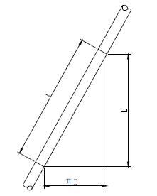
Figure (2) Expansion diagram of a pitch spiral
L is the cable pitch, D is the cable diameter, and l is the actual length of the insulated core within one pitch. Then the winching rate can be expressed by the following formula:
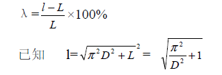
In the formula, m——cable pitch factor;
Therefore, the twisting rate λ can be written as:
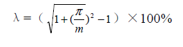
It can be seen that the twisting rate is determined by the pitch factor. The smaller the pitch factor, the greater the twisting rate. The increase in the twisting rate increases the resistance of the cabled wires and correspondingly increases the consumption of conductor materials and other insulating materials per unit length of the cable.